| |
|

|
Step 1: |
|
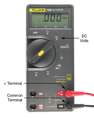
Set the function switch on the DMM to Ohms ( )
return the positive meter lead to the Volts/Ohms terminal.
Touch the two probes together.
The meter should read zero resistance.
If it reads more than a few tenths of an ohm, check for poor connections
or have your meter serviced.
)
return the positive meter lead to the Volts/Ohms terminal.
Touch the two probes together.
The meter should read zero resistance.
If it reads more than a few tenths of an ohm, check for poor connections
or have your meter serviced.
|
Step 2: |
|
Select several resistors at random from your parts kit.
For each resistor,
determine its nominal value from the
color code,
then
measure its resistance by touching one probe to each lead of
the resistor.
Do the nominal and measured values agree?
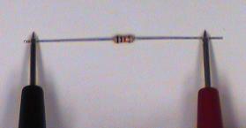
The most accurate way to do this (especially for large value
resistors) is to lay the resistor on the bench and pinch the
leads between the benchtop and the probe tip.
Like this:
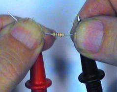
 What's wrong with holding the leads and probes between your fingers?
|
Diversion: |
|
Components that we will be using are marked so as to show the
tolerance
or accuracy of their manufacturing process.
A resistor marked red-red-red-gold, for example, is a 2.2 k
resistor with a 5% tolerance.
This means that the actual value of this resistor is ``guaranteed'' to be
between 2090 and 2310 ohms.
This guarantee is enforced by quality control procedures at the factory.
Often, the resistance is much closer than that specified.
|
Question 1: |
|
Formally, the actual resistance  of a resistor having nominal value
 and tolerance
  lies in the range
 .
Assuming common nominal and tolerance values, what is the tolerance of a series connection of two such resistors? of a parallel connection?
.
Assuming common nominal and tolerance values, what is the tolerance of a series connection of two such resistors? of a parallel connection?
|
Step 3: |
|
Obtain ten resistors with the same marked value
(your parts kit should have 10 1k
resistors).
Measure the resistance of each resistor.
Note each resistor's value and compare it to its nominal value.
Within the accuracy of the ohmmeter, does your "batch" have the stated accuracy?
|
Question 2: |
|
Calculate the average resistance (
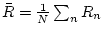 ). What is the greatest measured excursion from the mean?
Does it lie within the specified tolerance?
). What is the greatest measured excursion from the mean?
Does it lie within the specified tolerance?
|
Question 3: |
|
How do we know which is more nearly correct: the DMM
or the labels on the resistors?
|
Step 4: |
|
Holding the ohmmeter's leads, one in each hand, measure your own resistance.
How stable is the ohmmeter's reading?
If the reading varies somewhat, the resolution of your measurement is limited to the digit that changes least often;
what is the resolution of your resistance?
|
Step 5: |
|
Does your resistance change when you wet your fingers?
If so, speculate why.
Calculate what voltage would be necessary to
produce a 5 mA current through you.
(Why 5 mA? See Lab 0.)
|
Step 6: |
|
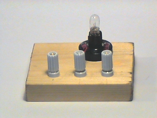
Using the DMM,
measure the resistance of the light bulb.
Does this correspond too the value you would expect
from Ohm's Law given the values of voltage and current
you measured in Parts 1 and 2?
Caution
The DMM can only measure the resistance when the
element being measured is disconnected from the circuit.
Attempting to measure a resistor which is part of a circuit
will give erroneous results.
|
|
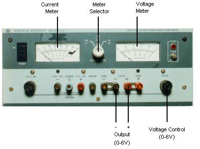
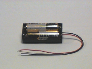
For this measurement, we will need to vary the voltage
applied to the bulb, so we will need a variable voltage source.
This is provided by the
DC Power Supply
The DC power supply actually contains three variable voltage sources,
but we will be using only one of them, the 0-6V supply.
| |
|
|
Step 1: |
|
Set up power supply:
Remove all connections from the output terminals,
turn both voltage controls to zero (fully counterclockwise),
set the meter selector to the 6V supply.
|
Step 2: |
|
Set the DMM to the DC Volts function.
Connect the black (-) probe to the black 0-6V output terminal
and the red (+) probe to the red terminal
(you may need your lab partner for this).
|
Step 3: |
|
Turn on the power supply.
Slowly increase the output voltage by turning the 0-6V voltage
control clockwise.
Both the Voltage meter on the power supply and the DMM should
show increasing voltage values.
For several different values, note both the power supply meter
and the DMM reading.
How do the two compare?
|
Step 4: |
|
Return the voltage output to zero.
|
Note: |
|
For the rest of this part you will need to borrow a second
DMM from another lab group.
If you like, you can pool resources and both groups
make these measurements together.
|
Step 5: |
|
Wire the circuit below.
The easiest way to do this without running out of hands
is to use banana plug patch cords
(they fit in the DMM if you unplug the probes).
![\includegraphics[scale=0.650000]{flashlight3.ps}](img154.png)
|
Step 6: |
|
Measure the current for voltages between 0 V and 1 V,
in steps of about 0.2 V.
and between 1 V and 5 V in steps of about 0.5 V.
It is not necessary to have V exactly equal to 1.000, 1.500, etc.
Just get it close and write down the numbers accurately.
|
Step 7: |
|
Plot I as a function of V.
How?
|
Question 4: |
|
To what point on this curve does the value of resistance
you measured with the ohmmeter correspond?
|
Step 8: |
|
Repeat the previous two steps using a 1000 ohm
(brown-black-red)
resistor
in place of the light bulb.
(Use the center and left hand binding posts to hold the
resistor as shown in the figure.)
Measure and plot I vs. V for a 1000 ohm resistor.
Is our assumption that I=V/R for all V a valid one?
|
Step 9: |
|
When finished, turn off the DMM to prevent running down its
battery.
Return the borrowed DMM.
|
![\includegraphics[scale=0.650000]{flashlight1.ps}](img152.png)
![\includegraphics[scale=0.650000]{flashlight4.ps}](img153.png)