ELEC 242 Lab
Experiment 10.1
Building the Motor Controller
New Components
- 4013 CMOS Flip-Flop
- Capacitor: 100
 F
F
- Resistors: 3.3 k
 ,
33 k
,
100 k
,
2-1 M
,
33 k
,
100 k
,
2-1 M
- Potentiometers: 1 k
, 10 k
The "only" thing we have to do in this lab is
to control the receiver motor
to synchronize it with another
camera, rather than driving it directly from a voltage source.
Unfortunately, there are several new components we need to do this,
so we have a bit of wiring to do before we can proceed.
The synchronization technique we will use is called a
Phase Locked Loop
(PLL).
The name pretty much describes how it works:
It is a closed loop feedback system where the frequency of one
signal (the sync pulses from the receiver disk) is controlled
(by varying the speed of the receiver motor) so that it is
"locked" in phase with another signal
(the sync pulses from the transmitter disk).
There are three basic components in this motor control circuit:
the phase detector, the loop filter, and the motor amplifier.
Here's how they fit together:
Since you are going to connect your receiver to another camera,
and since there is only one camera/receiver per lab group,
you will have to find another group to act as your transmitting
station when you are ready to receive.
Since we have both 6 ft. and 25 ft cables, you have considerable
freedom in choosing a partner for this lab.
Part 1: Preliminary Test
| |
|

|
Step 1: |
|
Verify that your system still works by repeating steps
1 and 2 of
Experiment 9.2.
|
Part 2: Motor Driver
The first step is to connect the motor to the motor
amplifier instead of the 0-6 V power supply.
This is what we'll have when we're finished:
 If you have kept your circuitly from Labs
7 and 8, you have
most of this already: It's just the summing amplifier with
a new feedback resistor and one of the inputs eliminated.
If you have kept your circuitly from Labs
7 and 8, you have
most of this already: It's just the summing amplifier with
a new feedback resistor and one of the inputs eliminated.
| |
|
|
Step 1: |
|
Disconnect the motor (pin 52 of the interface board socket strip)
from the 0-6 V power supply (pin 30) and connect it to the output
of the motor amplifier.
|
Step 2: |
|
If you have kept your summing amplifier from Labs 8 and 9,
modify it by replacing the feedback resistor  with a
100 k
resistor and removing the 330 k
resistor.
If not, replace it with the following circuit
with a
100 k
resistor and removing the 330 k
resistor.
If not, replace it with the following circuit

|
Step 3: |
|
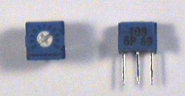
Select a 1k
potentiometer from your parts kit.
It will have three short wires sticking out the bottom in a
triangular pattern.
The center terminal is the slider contact and the two outer terminals
are the fixed contacts.
|
Note
Figuring out the value of a pot can be tricky.
Some pots are labeled directly with the value
(e.g. "100" or "10K").
Others are labeled using the same code as for fixed resistors,
execpt that numbers, rather than colors, are used.
For example, a 1k
resistor would have the bands
brown-black-red. The values of these colors are 1, 0, and 2,
so a 1k
pot would have the label "102"
|
|
Step 4: |
|
We will use this potentiometer, instead of the control on the
power supply, to set the speed of the motor.
Since the summing amplifier is inverting, we need something we can
adjust to about -4 V.
Wire the following adjustable voltage divider near to the summing
amplifier.
|
Step 5: |
|
Connect  from the speed control to the appropriate input of
the summing amplifier.
Make sure nothing is connected to
from the speed control to the appropriate input of
the summing amplifier.
Make sure nothing is connected to  (it was
  in Labs
8 and 9 and was connected to D/A channel 1).
Your motor amplifier circuit should now look like this:
in Labs
8 and 9 and was connected to D/A channel 1).
Your motor amplifier circuit should now look like this:
|
Part 3: 15 Volt Sync Pulse
The phase detector is a CMOS flip-flop
with logic levels of
+15 V and ground.
Fortunately the sync circuit we already have produces a 15 V
pulse as well as a 5 V pulse.
All we need to do is give it a name.
Time to test what we've done so far.
| |
|
|
Step 1: |
|
Turn on the power supply.
The disk should be
rotating in a clockwise direction as
seen from the front of the camera.
|
Step 2: |
|
Connect  to Channel 1 of the scope.
|
Step 3: |
|
Adjust the
speed control
potentiometer until the signal has
a frequency of exactly 30 Hz.
|
Part 4: Phase Detector
The phase detector is a flip-flop which is set
on the rising edge of the transmitter (camera)
sync pulse and cleared on the rising edge of the
receiver sync pulse.
If the two signals are exactly 180 degrees out of phase
(which is the condition we want, since the viewer lens is
separated from the camera lens by 180 degrees)
then the output  will be a square wave (i.e. it will
have a 50% duty cycle)
with an average value of 7.5 V.
If the receiver gets ahead of the camera (i.e. its sync pulse
comes too early) the wave form will be at 0 V longer than it
will be at 15 V and its average value will decrease.
Similarly, if the receiver gets behind the camera, the average
value of
will increase.
Since both the loop filter and the motor summing amplifier
are inverting,
increasing
will increase the speed of the
receiver motor to catch up with the transmitter
and decreasing
will allow it to fall back,
exactly the situation we want.
will be a square wave (i.e. it will
have a 50% duty cycle)
with an average value of 7.5 V.
If the receiver gets ahead of the camera (i.e. its sync pulse
comes too early) the wave form will be at 0 V longer than it
will be at 15 V and its average value will decrease.
Similarly, if the receiver gets behind the camera, the average
value of
will increase.
Since both the loop filter and the motor summing amplifier
are inverting,
increasing
will increase the speed of the
receiver motor to catch up with the transmitter
and decreasing
will allow it to fall back,
exactly the situation we want.
| |
|
|
Step 1: |
|
Get a 4013 CMOS flip-flop chip.
Its pins are numbered like this:
|
Step 2: |
|
Wire the phase detector circuit.
Be sure to connect power and ground.
|
Step 3: |
|
To prevent damage to the chip, connect the unused inputs
(pins 3, 4, 5, and 6) to ground.
|
Part 5: Loop Filter
Two things are wrong with the phase detector output:
Although the average value reflects the phase difference,
the signal itself is either +15 V or 0,
i.e. it needs to be smoothed.
Also, when the two signals are properly aligned
(180 degrees apart), this average value is 7.5 V.
But our motor driver circuit is designed so that when the
motor is running at the proper speed, the correction voltage is
zero,
i.e. we need to shift the signal by -7.5 V.
If we make the amount of shift variable, then we can control the
amount of offset between the camera and receiver disks.
Then we will have a position control to center the received image.
| |
|
|
Step 1: |
|
Wire the loop filter circuit:
|
Step 2: |
|
Connect
from the phase detector output to the loop filter input.
Don't connect
to the motor driver yet.
|
Step 3: |
|
Turn on the power
And adjust the position control potentiometer to
-7.5 V.
|