|
| ||
Step 1: |
Wire the following summing amplifier circuit.
|

|
This circuit forms the difference between the measured value of
the shaft angle, represented by | ||
Question 1: |
Write an expression for | |
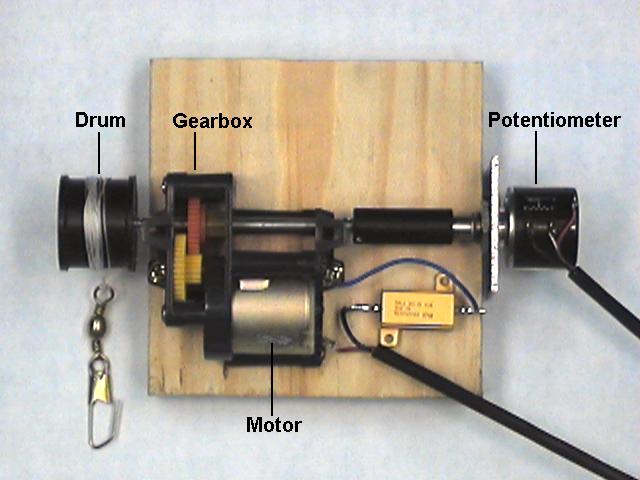
Step 2: |
Get a
motor-gearbox assembly
from the cart.
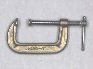
Use a
C-clamp
to clamp it to the edge of the bench with the spool hanging over the
edge.
The string should be wound clockwise around the spool
(i.e. it should hang off the right side of the spool).
We can consider this apparatus as either a model of an elevator
or the prototype for a robot ice fisher.
| |
Step 3: |
Plug a
phone plug patch cable
into P4 of the interface board.
Plug the other end into the connector on the potentiometer on the
motor-gearbox.
| |
Step 4: |
By hand turn the spool counter-clockwise until it stops.
| |
Step 5: |
Turn on the power supply.
Measure the voltage | |
Step 6: |
While watching | |
Step 7: |
Turn the spool clockwise until it stops.
|
| |||
Step 1: |
Plug a phone plug patch cord into P6 on the interface board.
Connect the other end of the patch cord to the 3-pin connector of the
motor on the motor gearbox assembly.
| ||
Step 2: |
Ground one side of the motor (pin 36 on the interface
board socket strip).
Connect the other terminal of the motor (pin 37) to the motor
amplifier output.
| ||
Step 3: |
Connect D/A channel 1 (pin 11) to the motor amplifier input. |

|
| ||
Step 4: |
Connect A/D input 5 (pin 6 on the interface board socket strip)
to | |
Step 5: |
Load and start the "Controller 1" Labview program.
| |
Step 6: |
Turn on the power supply.
| |
Step 7: |
Rotate the drum on the motor-gearbox.
The value of
Vact
on the controller panel should change.
Continue rotating the drum in the appropriate direction until
Vact
is about -2.5 V.
| |
Step 8: |
Move the Drive Voltage slider upwards slowly until the motor starts to turn. The drum should turn counterclockwise and Vact should increase towards zero. If the drum turns clockwise, reverse the connections to the motor. |